[Top] [Prev] [Next] [Bottom]
This chapter uses an example to demonstrate how to configure a PortMaster for remote dial-in access to local hosts and networks. Although the example shows how Internet service providers (ISPs) can provide dial-in access to their users, this application can be used by academic environments, corporate telecommuters, or anyone else needing remote access to a host or network.
In this example, multiple asynchronous ports are configured with modems for answering incoming calls from users who then access a networked host connected via Ethernet to a PortMaster 2E Communications Server.
The following topics are described:
The PortMaster configuration described in this example (see Figure 17-1) allows up to seven 30-port PortMaster Communications Servers to be connected together to provide up to 210 dial-in asynchronous ports. The PortMaster Communications Server allows dial-in users to access a host for shell accounts and/or PPP, SLIP, or Compressed SLIP (CSLIP) connections.
ISPs can use this example to configure their PortMaster products to allow dial-in users to access hosts and networks. The number of ports used is a function of the number of expected subscribers. One port per 10 subscribers is the typical ratio, but peak usage and average usage per port should be monitored closely to determine the need for additional ports. RADIUS Accounting can help you to evaluate port usage. See the RADIUS Administrator's Guide for more information.
The same application can be used by companies to allow remote users to access their own accounts on the corporate network. Once the PortMaster authenticates users, they can access network resources as if they were connected to the corporate network directly.
Although this example uses seven PortMaster 2E Communications Servers, many more can be used. With more than seven PortMaster Communications Servers, the configuration is the same except that the assigned pools must be arranged differently.
Dial-In User Configuration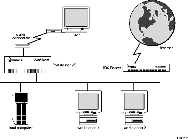
The example described in this chapter uses the values shown in Table 17-1. Change variable values to values that reflect your network.
You can set the assigned pool numbers a little closer together as long as they do not overlap; however, having the pools fall within bit boundaries makes packet filters easier to write.
Note ¯  This example uses a PortMaster 2E Communications Server. If you are using a PortMaster 25, the numbers of assigned pools can be moved closer together.
To install your PortMaster, follow the instructions in your hardware installation guide. If you need additional help, refer to the troubleshooting chapter of your installation guide. The example in this chapter shows variables in italics. Change these values to reflect your network.
Once you have assigned an IP address to the first PortMaster, continue with the following steps:
-
Connect modems to the PortMaster 2E (page 17-5).
-
Configure global settings (page 17-5).
-
Configure Ethernet interface settings (page 17-6).
-
Configure asynchronous port settings (page 17-6).
-
Configure modems for the asynchronous ports (page 17-6).
-
Configure users via RADIUS settings if you have more than one hundred users (page 17-8).
-
Configure login users if you are not using RADIUS (page 17-9).
-
Configure network users if you are not using RADIUS (page 17-10).
-
Repeat Steps 1 through 8 for each additional PortMaster in your topology.
Note ¯  This example describes how to configure the first PortMaster, pm1.edu.com. Use a similar configuration for the remaining PortMaster devices.
Use the following steps to connect modems to the first PortMaster:
-
Connect your modems to the serial ports using straight-through modem cables.
-
Modems slower than 14.4Kbps are not recommended for network users.
-
Make sure that the modem cables are securely fastened and that you provide enough room for the modems to stay cool.
Configure the global settings on the first PortMaster to the values shown in Table 17-2.
For more information about global settings, refer to Chapter 3, "Configuring Global Settings."
After configuring the global settings as shown in Table 17-2, save the configuration using the following command:
You must configure each port you are using for dial-in on the first PortMaster, plus its attached modem.
Set the Ethernet port on the first PortMaster to the values shown in Table 17-3.
Once you have configured the Ethernet interface as shown in Table 17-3, save the configuration using the following command:
For more information on Ethernet settings, refer to Chapter 4, "Configuring the Ethernet Interface."
The serial modem ports are designated S0 through S29 on the PortMaster. Use the set all command to set the same values for each serial port. The port values shown in Table 17-4 can be set on all asynchronous ports on the first PortMaster. Use the modem table described in Chapter 10, "Using Modems," to configure the attached modems, or set each port as a host device as described in Chapter 18, "Accessing Shared Devices," and configure each modem individually.
Note ¯  V.34 modems should lock the DTE rate at 115200bps unless your modem manual instructs otherwise. V.32bis modems should lock the DTE rate at 57600bps. Use the fastest DTE interface speed supported by your modem.
A list of modems and their initialization strings appears in Chapter 10, "Using Modems." The recommended configuration for this example has the following features:
Only hundred or so users can be configured in the user table and stored in the nonvolatile memory of the PortMaster. Therefore, use RADIUS for user authentication when you must configure multiple PortMaster Communication Servers to handle more than a few dozen users. This example assumes the use of RADIUS.
If you are not using RADIUS, configure dial-in and network users in the user table.
The RADIUS settings for the first PortMaster are given in Table 17-5. However, for information about RADIUS and its parameters, refer to the RADIUS Administrator's Guide or access the information via FTP from ftp://ftp.livingston.com/pub/le/radius/radius.install
.
Once you have configured RADIUS settings as shown in Table 17-5, save the configuration using the following command:
Note ¯  Use the instructions in this section only if you are not using RADIUS and you are not using pass-through logins.
A user account must be set up on the PortMaster for each authorized user. You should configure each new user user1, user2, and so on, with the values shown in Table 17-6.
Once you have configured user table settings as shown in Table 17-6, save the configuration using the following command:
For more information about configuring user table values, refer to Chapter 7, "Configuring Dial-In Users."
Note ¯  Use the instructions in this section only if you are not using RADIUS.
A user account must be set up on the PortMaster for each authorized network user. Each new user usera, userb, and so on should be configured with the values shown in Table 17-7.
You can also use SLIP or CSLIP instead of PPP. Refer to Chapter 7, "Configuring Dial-In Users," for more information about this configuration.
Once you have configured user table settings as shown in Table 17-7, save the configuration using the following command:
For more information about configuring user table values, refer to Chapter 7, "Configuring Dial-In Users."
To test the configuration, follow these steps for each PortMaster set up for user dial-in access:
-
Enter the following commands:
-
Dial in to the PortMaster you are testing, using the username and password you have created in either RADIUS, or the user table.
-
If everything connects as expected, turn off debugging and save the configuration:
-
If you notice a problem, do the following:
a. Reset the port.
b. Check your configuration.
c. Dial the PortMaster again.
d. Repeat this procedure until the connection is made correctly.
-
When you have configured the PortMaster correctly, reset the ports and save the configuration:
[Top] [Prev] [Next] [Bottom]
spider@livingston.com
Copyright © 1998, Livingston Enterprises, Inc. All rights
reserved.